Common Temperature Control Mistakes That Waste Energy and Comfort
On this page 7 sections
- How Temperature Controllers Work
- How Sensor Types Affect Controller Accuracy and Stability
- What Control Algorithms Mean for Comfort and Energy Use
- How Controllers Interface With Different Heating and Cooling Devices
- Troubleshooting Common Temperature Controller Issues
- How Remote Setpoint Inputs and Advanced Features Improve Control
- Questions People Ask
Temperature controllers are devices that regulate temperature by comparing a measured value to a desired set point and activating heating or cooling systems to keep the environment stable. They rely on temperature sensors like thermocouples, thermistors, or RTDs to detect current conditions and use control methods tailored to the precision and speed needed.
Understanding how different controllers and sensors work together helps you pick the right system for comfort, safety, and energy efficiency in your home or industrial setup.
How Temperature Controllers Work
Temperature controllers regulate temperature by comparing a measured value from a sensor to a preset target called the set point, then adjusting heating or cooling devices to maintain that temperature. They do this using control methods like On/Off, Proportional, and PID control to keep temperatures within a narrow, acceptable range.
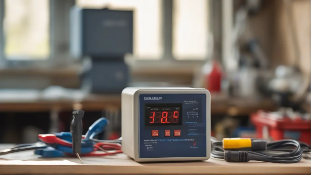
A temperature controller’s job starts with a sensor that measures the current temperature. Common sensors include thermocouples, thermistors, and Resistance Temperature Detectors (RTDs). Thermocouples generate a voltage based on temperature differences, thermistors change resistance with temperature usually decreasing resistance as temperature rises (Negative Temperature Coefficient or NTC), and RTDs increase resistance with temperature (Positive Temperature Coefficient or PTC). These sensors feed real-time data to the controller.
The controller compares the sensor reading to the set point — the temperature you want to keep. It then decides how to adjust the heating or cooling output. The simplest method, On/Off control, switches the device fully on or off once the temperature crosses a threshold. This causes the temperature to swing around the set point, often by 2-5% or more, because the heater or cooler fully cycles rather than modulating output.
Proportional controllers adjust output power in proportion to the temperature difference from the set point. If the temperature is far from the target, the output is high; as the temperature nears the set point, the output decreases smoothly. This reduces temperature swings compared to On/Off control but can still allow some steady-state error where the temperature stabilizes slightly off the set point.
PID controllers add integral and derivative calculations to proportional control. The integral part corrects steady-state errors by integrating past differences over time, while the derivative part anticipates future changes by measuring the rate of temperature change. This approach keeps temperature very close to the set point with minimal overshoot and oscillation, making PID the most precise control method for sensitive heating or cooling applications.
For example, an On/Off controller set to 70°F might let the temperature swing between about 68.5°F and 71.5°F. A proportional controller narrows this range, perhaps to within 1°F of the set point. A well-tuned PID controller can hold temperature to within a fraction of a degree. These differences matter when you need precise control, such as in fermentation chambers or laboratory incubators.
Temperature controllers regulate cooling devices like thermoelectric coolers by reversing current flow to transfer heat away. This lets the controller both heat and cool a space, maintaining a stable set point. This is how they prevent temperature fluctuations that can cause problems like condensation or, metaphorically, “acid rain” damage in sensitive equipment by maintaining stable environmental conditions.

How Sensor Types Affect Controller Accuracy and Stability
Checking if your temperature sensor works without connecting it to a microcontroller starts with basics: measure its resistance or voltage output with a multimeter at known temperatures, like ice water (32°F) and boiling water (212°F). The readings should change predictably—no sudden jumps or infinite resistance—which confirms the sensor responds to temperature changes.
Temperature control depends on accurate sensing. Different sensors vary widely in how precisely and quickly they measure heat, influencing how stable and responsive the controller can keep the set point.

Thermocouples generate a voltage proportional to temperature difference at their junctions. They handle extreme temperatures and respond fast but have lower sensitivity and less linear output, requiring compensation in the controller for precise control.
Resistance Temperature Detectors (RTDs) use metals like platinum whose resistance increases with temperature—a Positive Temperature Coefficient (PTC). RTDs provide excellent linearity and stability over a wide range but react slower than thermocouples.
Thermistors are semiconductor resistors with either Negative Temperature Coefficient (NTC), where resistance decreases as temperature rises, or less commonly, PTC behavior. NTC thermistors are highly sensitive with fast response but exhibit nonlinear resistance changes, needing curve-fitting algorithms for accuracy.
Response time matters when a sensor must track rapid temperature changes. Thermocouples typically respond in milliseconds, thermistors in tenths of a second, and RTDs can take several seconds due to their construction.
Linearity affects how directly sensor output correlates with temperature. RTDs are most linear, simplifying controller calculations. Thermocouples and thermistors require more complex correction, which some controllers handle internally.
Sensitivity defines how much the sensor output changes per degree of temperature shift. Thermistors are most sensitive, detecting small changes well but at the cost of linearity. Thermocouples are less sensitive, which can limit precision at low temperatures.
Choosing the right sensor shapes controller performance. For finely tuned temperature control with minimal overshoot, an RTD paired with a PID controller is ideal. Thermocouples suit harsh environments where speed and range matter more than perfect accuracy. Thermistors work well in systems needing quick response and high sensitivity but tolerate some nonlinearity.
Poor sensor selection or a damaged sensor causes unstable control, with temperature swings or delayed reactions. Sensor placement and wiring quality also influence accuracy; a loose connection or improper insulation can mimic sensor failure.
Temperature controllers rely on the sensor’s signal to modulate heating or cooling devices, so the sensor’s physical and electrical properties directly affect how well the controller maintains a stable temperature near the set point.
For deeper understanding of sensor operation and selection, see how temperature sensors work, including thermocouples, RTDs, and thermistors, with their applications and technology nuances how does a temperature sensor work.

What Control Algorithms Mean for Comfort and Energy Use
Temperature control quality and energy efficiency depend heavily on the algorithm the controller uses. On/Off, Proportional, and PID controllers each respond differently to temperature changes, affecting comfort, energy use, and equipment wear.
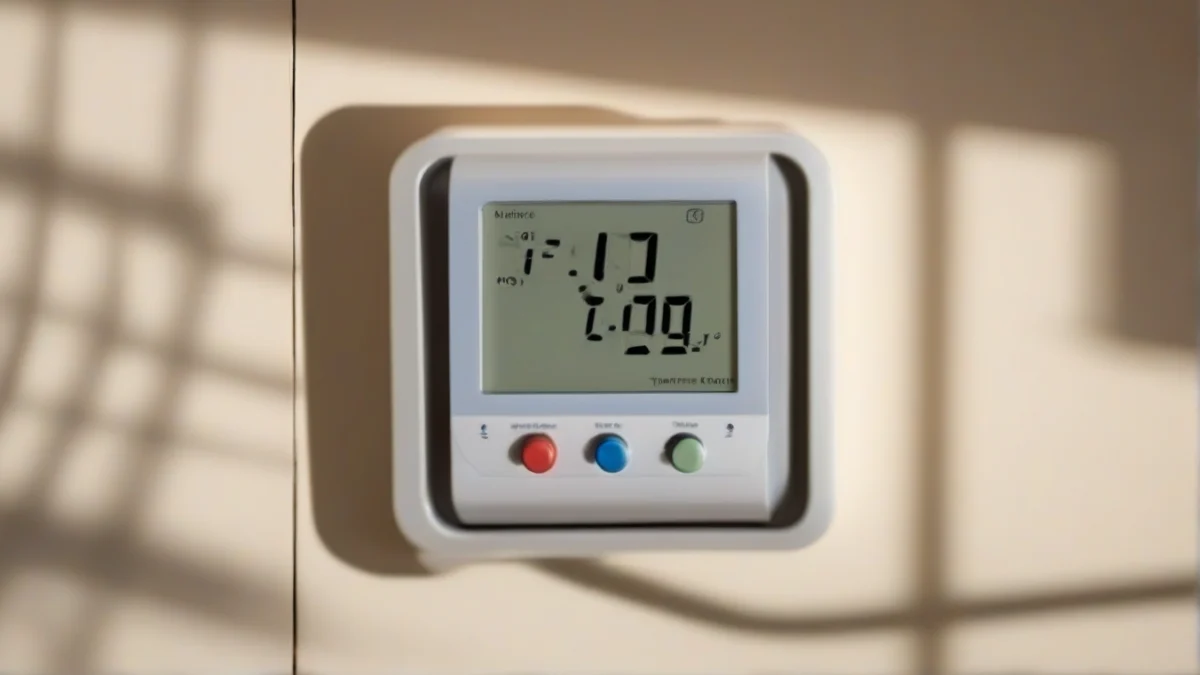
On/Off controllers switch heating or cooling fully on when the temperature falls below the set point and turn it off once the target is reached. This simple approach causes temperature swings typically between 2% and 5% around the set point. For example, a room set to 70°F might cycle between about 68.6°F and 71.4°F before switching states. This cycling wastes energy and creates noticeable temperature fluctuations.
Proportional controllers reduce these swings by adjusting output power in proportion to the difference between the measured temperature and the set point. Instead of a binary on/off, the controller might run a heater at 50% power if the temperature is 2°F below target. However, to avoid constant switching near the set point, proportional controllers include a deadband, a small temperature range—often 1°F or less—where the output remains steady or off. This reduces wear on relays but means the temperature can settle slightly away from the exact set point.
PID controllers offer the most precise control by combining three calculations: proportional (P) reacts to current temperature error; integral (I) sums past errors over time to eliminate steady offsets; and derivative (D) predicts future trends by measuring the rate of temperature change. This trio smooths output, minimizing overshoot and reducing the time the temperature spends away from the set point. For instance, a PID controller can maintain a 0.1°F variance around the target, delivering steady comfort and saving energy by preventing overheating or overcooling.
Energy efficiency improves progressively from On/Off to Proportional to PID control. On/Off wastes energy cycling full power, while Proportional and PID modulate output to match need. PID’s integral function corrects persistent errors that Proportional alone can’t, avoiding unnecessary fuel or electricity use.
Wear on mechanical components also varies. On/Off controllers cause frequent cycling, shortening the life of relays and switches. Proportional control reduces cycling by spreading output over a range, but some mechanical wear remains. PID controllers often use solid-state outputs or modulate power smoothly, greatly extending component life.
Understanding deadband is key to grasping Proportional control. It creates a buffer zone where small deviations from set point do not trigger output changes, preventing rapid on/off switching. For example, with a 1°F deadband around 70°F, the heater might only activate if temperature drops below 69.5°F and turn off above 70.5°F. This trade-off sacrifices exact temperature for less wear and noise.
Each PID component serves a distinct purpose. The proportional term adjusts power based on immediate error size. The integral term accumulates error over time, correcting biases like heat loss. The derivative term counteracts rapid changes, dampening oscillations and preventing overshoot. Tuning these terms properly is essential to avoid instability or sluggish response.
Choosing the right algorithm depends on your comfort needs and system characteristics. On/Off is acceptable for simple or rugged applications where ±2°F swings are tolerable. Proportional control suits moderate precision needs, balancing comfort and component life. PID is the best choice when narrow temperature tolerance, energy savings, and equipment longevity matter, especially in critical or sensitive environments.
How Controllers Interface With Different Heating and Cooling Devices
Temperature controllers regulate both heating and cooling by sending signals to actuators that change the temperature in response to sensor input. The controller reads the temperature sensor—often a thermocouple, thermistor, or RTD—which converts heat into an electrical signal based on resistance or voltage. This signal guides the controller’s output to maintain the set point temperature precisely.
Common actuators include resistive heaters and thermoelectric coolers. Resistive heaters generate heat when electric current passes through their resistance wire. The controller modulates power to these heaters by switching them on or off rapidly (pulse-width modulation) or by varying current levels in proportional control systems. This adjustment keeps temperatures within tight limits without wasting energy.
Thermoelectric coolers, or Peltier devices, work differently. They use the Peltier effect to pump heat from one side to the other when current flows, providing cooling or heating depending on the current direction. A temperature controller reverses the current to switch between heating and cooling modes, enabling precise temperature regulation even below ambient.
A summing amplifier inside the controller plays a key role in accurate temperature control. It combines the sensor signal with the set point and feedback from the actuator, amplifying the difference to produce a control output. This feedback loop minimizes error and stabilizes temperature by adjusting power smoothly rather than switching abruptly.
Some controllers manage both heating and cooling simultaneously using separate outputs. For example, in climate chambers or sensitive incubators, the controller activates a heater when the temperature drops below the set point and a thermoelectric cooler or refrigeration system when it rises above, keeping temperature swings within a narrow deadband.
The way a temperature sensor works is critical to this process. Thermistors typically have a Negative Temperature Coefficient, meaning their resistance drops as temperature rises, giving a nonlinear but sensitive response. RTDs have a Positive Temperature Coefficient, with resistance increasing linearly with temperature, offering stability and accuracy over a wide range. The controller translates these resistance changes into temperature readings to decide how much power the actuator needs.
Troubleshooting Common Temperature Controller Issues
If your Edna temperature controller isn’t heating up, start by checking the sensor wiring and connection quality. Loose wires or corrosion at terminals often cause false readings or no heat output.
To check if your temperature sensor works without connecting it to a microcontroller, measure its resistance or voltage with a multimeter at known temperatures. For example, a thermistor’s resistance decreases as temperature rises, so if resistance doesn’t change at room temperature and after warming it slightly, the sensor may be faulty.
Common sensor failure modes include open circuits, short circuits, and degraded response due to contamination or mechanical damage. Look for broken leads, discolored insulation, or inconsistent readings.
Controller output faults often show as relays that never click or remain stuck. Use a multimeter to check relay coil voltage and confirm the relay switches when the set point is reached. The relay contacts should have near zero resistance when closed and infinite resistance when open.
Verify the set point and any remote input signals by comparing what the controller display shows with your desired temperature target. Remote inputs can come from external potentiometers or digital signals; wiring errors here can prevent proper heating or cooling.
Wiring a gas infrared heater with an electrical ignition, starter solenoid valve, and STC-3008 dual digital temperature controller involves connecting the controller’s relay outputs to the heater’s ignition and valve control terminals. The sensor input from the thermocouple or RTD must connect to the controller’s sensor port. Power lines should follow the controller’s voltage and current specs. Always follow the STC-3008 manual for relay wiring and use the correct polarity to avoid damage.
How Remote Setpoint Inputs and Advanced Features Improve Control
Remote setpoint inputs allow you to adjust the temperature target from an external device, like a computer or a wireless thermostat, rather than the controller itself. This adds flexibility for setups where manual changes are inconvenient or you want automated control.
Auto-tuning features help the controller learn the system’s heating and cooling response characteristics. The controller adjusts its PID parameters automatically to minimize temperature swings and overshoot, improving comfort and efficiency without manual tuning.
Cascade control uses two controllers in series: one regulates the temperature setpoint of another controller managing the heating element. This arrangement is common in industrial or large-scale heating systems for tighter control and faster response.
Fuzzy logic control adds a layer of decision-making that deals with uncertainty and non-linear responses better than classic PID. It helps when temperature changes are erratic or sensors provide noisy data, although it’s less common in simple home heaters.
Alarms and safety limits built into advanced controllers alert you if temperatures exceed safe thresholds or if sensors fail. For example, a wireless hot water temperature controller can notify you if the water temperature goes too high, preventing scald risks.
Pool heater controllers work best using water temperature sensors with stable response, such as RTDs. They provide accurate feedback to maintain pool temperatures around 78°F to 82°F, which is generally comfortable and energy efficient.