

Walk into any plant floor and you’ll see them: thermowells sticking into pipes, probe heads bolted to reactor jackets, and transmitters mounted on every other panel. These humble devices make or break your entire operation. A temperature reading that drifts by five degrees in a chemical reactor can ruin a batch worth tens of thousands of dollars. In a pharmaceutical cleanroom, it can trigger a full deviation investigation that stalls production for days.
This guide covers the practical side of industrial temperature measurement. You’ll learn how each sensor technology works, when to choose one over another, how to wire them into your control system, and how to keep them accurate for years. We’ll get into specific numbers, trade-offs, and failure modes that most articles skip. By the end, you’ll have a clear decision framework for your next sensor purchase or replacement cycle.
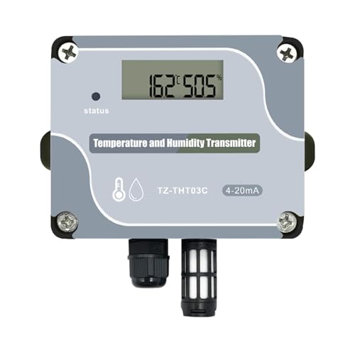
Tzone
Tzone 4-20mA Temperature Humidity Transmitter Industrial Analog…
- 4-20 mA Temperature Humidity Sensor: Analog signal output,makes the sensor has the characteristics of strong anti-interference abi…
- Measurement Range: Temperature measuring range is -40 ℃ to 125 ℃; Humidity measuring range is 5% to 95% RH; Power Supply Voltage i…
- 4-20 mA Temperature Transmitter: Adopts industrial grade CMOS chip SHT30 sensor, which improves its stability and reliability in h…
One useful option for many monitoring applications is the Tzone 4-20mA Temperature Humidity Transmitter, which combines an SHT30 CMOS sensor with a 4-20 mA analog output in a wall-mount enclosure. It’s a solid fit for cleanrooms, server rooms, and storage areas where you need reliable data fed straight into a PLC or SCADA system.

Why Temperature Sensors Matter in Process Control
Temperature is the most measured process variable in industry. It affects reaction rates, product viscosity, material properties, and energy consumption. In a distillation column, a two-degree error can shift the separation point and send off-spec product downstream. In a food pasteurization line, an inaccurate reading creates a food safety risk that regulators take very seriously.
The control loop depends entirely on the sensor’s ability to report the true process temperature. A PID controller can only be as good as its feedback signal. If the sensor lags, drifts, or responds slowly, the controller will compensate incorrectly. That’s why sensor selection isn’t just an instrumentation detail — it’s a core process design decision.
Consider the cost of ownership. A cheap thermocouple might cost $30, but if it drifts out of tolerance every three months and requires calibration or replacement, the labor and downtime costs dwarf the initial savings. A higher-quality RTD at $200 might hold calibration for two years. The math usually favors the better sensor.
The Four Primary Temperature Sensor Technologies
Every industrial temperature sensor falls into one of four categories. Each has strengths and weaknesses that make it suitable for specific conditions. Here’s how they compare.
Thermocouples: Range and Ruggedness
Thermocouples work on the Seebeck effect: two dissimilar metals joined at a junction produce a small voltage proportional to temperature. They’re the workhorses of high-temperature applications. Type K covers -200°C to 1260°C, Type R and S go up to 1480°C, and tungsten-rhenium types reach 2300°C.
Their main advantage is ruggedness. You can weld them, bend them, and subject them to vibration without much concern. They respond quickly because the junction is small and has low thermal mass. But accuracy suffers. Standard limits of error for Type K is ±2.2°C or ±0.75%, whichever is greater. That’s fine for a furnace, not fine for a precision lab process.
Thermocouples also drift. The wire composition changes slightly with repeated thermal cycling, especially above 500°C. They’re also susceptible to electrical noise because the signal is only millivolts. You’ll need shielded cable and proper grounding to get reliable readings.
RTDs: Accuracy and Stability
Resistance temperature detectors (RTDs) measure temperature through the predictable change in electrical resistance of pure platinum. The standard PT100 has 100 ohms at 0°C. PT1000 variants have 1000 ohms at 0°C and offer better signal-to-noise ratio.
RTDs are the accuracy champions. A Class A PT100 achieves ±0.15°C at 0°C. They drift very little — typically less than 0.1°C per year. They’re stable across a wide range, from -200°C to 600°C for standard platinum elements. This makes them the default choice for critical process control, custody transfer, and quality assurance applications.
The downsides are cost and fragility. RTD elements are thin platinum wire wound around a ceramic or glass core. Vibration can break them. They also self-heat slightly because the measurement current passes through the sensing element. And they’re slower than thermocouples — the larger thermal mass means longer response time.
Thermistors: Sensitivity in Narrow Ranges
Thermistors are ceramic semiconductors with a large, nonlinear resistance change with temperature. A typical NTC (negative temperature coefficient) thermistor drops from 10,000 ohms at 25°C to about 1,000 ohms at 85°C. That’s a massive change, which makes them incredibly sensitive.
In a narrow range, say -40°C to 150°C, a thermistor can resolve temperature changes of 0.01°C. That’s why they appear in laboratory instruments and medical devices. But their nonlinearity requires lookup tables or polynomial equations to convert resistance to temperature. And they’re not interchangeable — a 10k thermistor from one manufacturer won’t match another’s curve exactly.
Industrial use is limited because of the narrow range and fragility. You won’t see thermistors in a 400°C process. You will see them in HVAC duct sensors, battery management systems, and other low-temperature applications where cost and sensitivity matter more than range.
IC Sensors: Integration and Linearity
Integrated circuit (IC) temperature sensors use silicon bandgap junctions to produce a voltage or current proportional to absolute temperature. The LM35 outputs 10 mV per degree Celsius. Digital versions like the SHT30 used in the Tzone transmitter communicate over I2C or similar protocols.
IC sensors shine in their linearity and ease of use. No cold junction compensation, no linearization circuits, no bridge balancing. They’re accurate to ±0.5°C or better in the -40°C to 125°C range. They’re also tiny and inexpensive.
The catch is their limited temperature range. Most ICs can’t survive above 150°C, so they’re useless for high-temperature processes. They also require a stable power supply and are more susceptible to electrical noise than an RTD in a shielded configuration. For cleanroom monitoring, HVAC control, and equipment condition monitoring, they’re an excellent choice.
How Temperature Sensors Communicate with Control Systems
A sensor that measures temperature is only half the equation. Getting that data into a PLC, DCS, or SCADA system requires a transmission method. This is where many engineers get tripped up, especially when retrofitting older plants.
Signal Conditioning and Transmission (4-20 mA, HART, Fieldbus)
The 4-20 mA analog loop remains the most common industrial standard. A transmitter converts the sensor’s resistance or voltage into a current proportional to temperature. 4 mA represents the low end of the range, 20 mA the high end. The beauty of current loops is their immunity to voltage drops — the signal stays accurate over long cable runs up to several thousand feet.
Three-wire and four-wire configurations exist. A four-wire loop has separate power and signal pairs, which eliminates lead resistance errors. Three-wire loops, like the one on the Tzone transmitter, share a common wire and are simpler to install. They’re accurate enough for most monitoring applications, though not quite as precise as four-wire for high-accuracy measurements.
HART (Highway Addressable Remote Transducer) superimposes a digital signal on the analog 4-20 mA loop. You get the reliability of analog with the ability to read diagnostics, configure ranges, and perform calibration remotely. It’s the de facto standard for smart transmitters in existing plants.
Fieldbus protocols like Foundation Fieldbus and Profibus PA are fully digital. They carry multiple variables on a single twisted pair and support advanced diagnostics. But they require specialized infrastructure and engineering expertise. For new plants, they’re worth considering. For retrofits, 4-20 mA with HART is usually the pragmatic choice.
The Control Loop: From Sensor to Actuator
Here’s the chain of events in a typical temperature control loop. The sensor measures process temperature. The transmitter converts that to a 4-20 mA signal. The PLC or DCS reads the signal, compares it to the setpoint, and runs a PID algorithm. The controller output goes to a final control element — usually a control valve, heater, or variable-frequency drive.
The sensor’s response time directly affects loop tuning. A slow sensor in a fast process creates phase lag, which forces you to detune the controller. The result is poor disturbance rejection and wider temperature swings. If you’re fighting oscillation in a loop, check the sensor’s time constant before touching the PID gains.
For a deeper look at how the whole control system fits together, check out this process control instrumentation overview.
Selecting the Right Sensor: A Decision Matrix
Choosing a sensor shouldn’t be a gut call. Use the table below to weigh your priorities. Score each factor from 1 to 5 based on your application’s needs, then compare totals.
| Factor | Thermocouple | RTD (PT100) | Thermistor | IC Sensor |
|---|---|---|---|---|
| Temperature range | -200°C to 2300°C | -200°C to 600°C | -40°C to 150°C | -40°C to 125°C |
| Accuracy (typical) | ±2.2°C | ±0.15°C | ±0.1°C | ±0.5°C |
| Stability / drift | Moderate drift | Very low drift | Low drift | Low drift |
| Response time | Fast | Moderate | Fast | Moderate |
| Relative cost | Low | High | Low | Very low |
| Vibration resistance | Excellent | Poor | Fair | Good |
| Linearity | Nonlinear | Nearly linear | Highly nonlinear | Linear |
| Best for | High-temp furnaces, exhausts | Process control, quality | Lab, narrow-range measurement | HVAC, equipment monitoring |
For most industrial process control applications, an RTD is the safe default. If you need to measure above 600°C, switch to a thermocouple. If you’re monitoring ambient conditions in a building or equipment room, an IC sensor with 4-20 mA output — like this Tzone transmitter — offers the best balance of cost and functionality.
Installation and Calibration: Best Practices for Accuracy
You can buy the best sensor in the world and still get garbage readings if the installation is wrong. Here’s what actually matters.
Insertion depth. The sensing element must be fully immersed in the process fluid. For pipes, insert the probe at least 10 times the pipe diameter, or angle it into the flow. In a 2-inch pipe, that’s 20 inches of insertion — often impossible. Use a thermowell with a reduced tip or install the sensor in a pipe elbow where the flow wraps around the probe.
Thermowell selection. Thermowells protect the sensor from pressure, corrosion, and flow. But they add thermal lag — the heat must pass through the well wall before reaching the sensor. A thin-walled stainless steel well responds faster than a thick carbon steel one. For fast processes, consider a stepped or straight-tapered well to minimize lag.
Heat transfer compound. Always fill the gap between the sensor and the thermowell bore with a heat-conductive compound or spring-load the sensor against the well tip. An air gap of even 0.5 mm can add seconds to the response time and cause measurement error.
Calibration frequency. RTDs should be calibrated annually in most plants. Thermocouples may need quarterly checks in high-temperature service. Use a dry-block calibrator or a stirred ice bath for reference. Document every calibration and track drift trends — a sensor that drifts consistently is a warning sign.
Electrical isolation. Ground loops are a common source of error in temperature measurement. Ensure the sensor sheath is properly grounded at one point only, and use isolated transmitters to break ground loops between the sensor and the PLC.
Troubleshooting and Predictive Maintenance for Temperature Sensors
Sensors fail in predictable ways. Knowing the failure modes helps you catch problems before they affect product quality.
Drift. The most common failure. The sensor reads correctly at ambient temperature but shifts at process temperature. Causes include thermal cycling, contamination of the sensing element, and aging of the wire. Detect drift through regular calibration. If you see a sensor drifting more than 0.5°C per year, plan for replacement.
Open circuit. A break in the sensor wire or the connection. The transmitter will typically output a high or low alarm value (upscale or downscale burnout). Check connections first — loose terminal screws are the usual culprit. If the wire is broken inside the probe, replacement is the only option.
Short circuit. More common in thermocouples where the two wires touch. The reading becomes erratic or pegged. Insulation breakdown at high temperatures is a frequent cause. Replace the probe and inspect the wiring for damage.
Moisture ingress. Water in the connection head causes corrosion and intermittent readings. Use sealed connectors and check the gaskets on the transmitter housing. The Tzone transmitter’s wall-mount design with a high-density shell is built to resist this in humid environments.
Modern smart transmitters with HART or Fieldbus can report sensor health diagnostics automatically. They track resistance changes, detect open or shorted elements, and flag when the sensor is out of calibration range. Using these diagnostics turns reactive maintenance into predictive maintenance — you replace the sensor during scheduled downtime, not during a batch.
What’s Next: Smart Sensors and Wireless Monitoring
The trend is toward sensors that do more than measure. Smart sensors with built-in diagnostics, local processing, and wireless communication are becoming standard in new installations. WirelessHART and ISA100.11a protocols let you add monitoring points without pulling cable, which is a huge cost saver in existing plants.
Cloud connectivity is also changing the game. Instead of a local historian, temperature data flows directly to analytics platforms that spot anomalies and predict failures. But don’t underestimate the cybersecurity implications — every connected sensor is a potential entry point for an attacker. Air-gapped networks are still common in critical infrastructure for good reason.
For a look at broader trends in temperature control technology, this article on future of industrial temperature control covers the landscape well.
What to Remember When Specifying Your Next Sensor
- Match the sensor to the process range. Don’t use a thermocouple where an RTD meets the range — accuracy matters more than range headroom.
- Budget for the full lifecycle. A $40 thermocouple that fails quarterly costs more than a $200 RTD that lasts two years.
- 4-20 mA analog output remains the most reliable and simplest way to interface with existing PLCs. HART adds diagnostics without changing the wiring.
- Installation quality determines real-world accuracy. Insertion depth, thermowell lag, and heat transfer compound are not optional details.
- Calibrate on a fixed schedule and track drift trends. A sensor that drifts consistently is telling you something.
- Use smart sensor diagnostics to move from reactive to predictive maintenance. The data is already there — use it.
- Consider the environment. Humidity, vibration, and electrical noise will kill a sensor faster than temperature extremes.
Frequently Asked Questions (FAQs)
What is the difference between a 2-wire and 4-wire RTD?
A 2-wire RTD measures the resistance of the element plus the resistance of the lead wires, which adds error. A 4-wire RTD uses two wires for current excitation and two for voltage sensing, completely eliminating lead wire resistance. If you need the best accuracy, use 4-wire. For moderate accuracy over short distances, 3-wire is a decent compromise. For a 4-20 mA transmitter, the transmitter does the signal conditioning, so the wiring configuration at the sensor matters less.
How often should I calibrate my temperature sensors?
It depends on the sensor type and process criticality. For RTDs in general process control, annual calibration is typical. For thermocouples in high-temperature service, quarterly checks are safer. For sensors in regulated industries like pharmaceutical or food processing, follow your validated schedule — usually every 6 to 12 months. Track the calibration results. If a sensor consistently passes with no drift, you can extend the interval. If it drifts, shorten it.
Can I connect a 4-20 mA temperature transmitter directly to my PLC?
Yes, provided the PLC has an analog input module configured for 4-20 mA current. You’ll need to set the range (e.g., -40°C to 125°C) in the PLC configuration to convert the current reading to a temperature value. Most modern PLCs handle this natively. Just make sure the transmitter’s power supply voltage matches the loop requirements — typically 12 to 30 V DC as with the Tzone unit.
What causes a temperature sensor to drift?
Drift comes from physical changes in the sensing element. For thermocouples, the alloy composition changes with thermal cycling and contamination. For RTDs, the platinum wire can strain or oxidize at high temperatures, changing its resistance. Moisture ingress and vibration also accelerate drift. Regular calibration is the only way to detect it early.
How do I choose between a thermocouple and an RTD for a new project?
Start with the maximum process temperature. If it exceeds 600°C, you need a thermocouple. If it stays below 400°C, an RTD gives you better accuracy and stability. For temperatures between 400°C and 600°C, weigh accuracy against cost — an RTD is more accurate but more expensive and fragile. Also consider vibration: if the probe will shake, a thermocouple survives; an RTD might not.

I am a mechanical engineer and love doing research on different home and outdoor heating options. When I am not working, I love spending time with my family and friends. I also enjoy blogging about my findings and helping others to find the best heating options for their needs.
Related guides
Industrial Temperature Sensors: The Key to Automation Efficiency
Temperature sensors for industrial automation monitor and control temperature in processes, ensuring efficiency, safety, and compliance in manufacturing…
Essential Temperature Sensors for Food Safety Compliance
Temperature sensors for food safety monitor and ensure proper cooking and storage temperatures, preventing foodborne illnesses and maintaining…

Essential Automotive Temperature Sensors for Peak Performance
You're chasing a misfire that only shows up after 20 minutes of highway driving. The factory gauge reads…