

You’re troubleshooting a process that runs hot, or maybe you’re designing a controller from scratch. The sensor you pick determines whether your system holds 100.0°C or drifts to 102.5°C. Get it wrong, and you’ll chase ghosts in the calibration log for months.
This guide covers the six sensor families you’ll actually encounter in the field: thermocouples, RTDs, thermistors, infrared, semiconductor ICs, and bimetallic/filled systems. You’ll get real numbers for range and accuracy, wiring pitfalls that trip up even experienced techs, and a decision matrix that narrows your options fast.
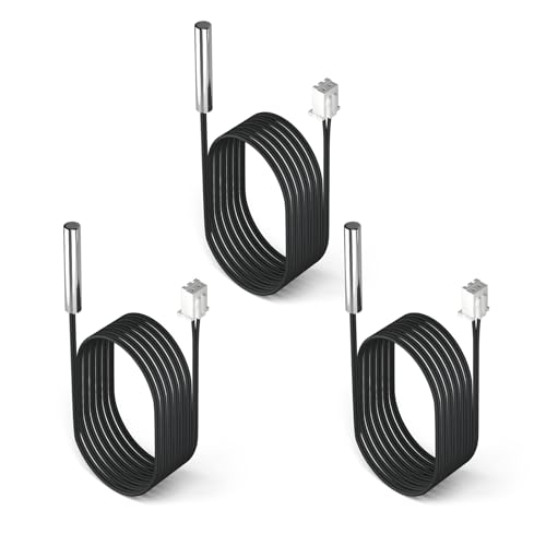
DROK
DROK 10K Temperature Sensor Probe 3pcs, 1…
- Advanced Technology: DROK smart sensors cable adopts sensitive and reliable NTC thermistor and connected by PVC wire, 1 meter lead…
- Wide Measuring Range: Our temperature probe is able to tolerate the widest measuring range (-25°c to 125°c (-13℉ to 257℉)).
- Stainless Steel Probe: This temperature sensor for car has 5*25mm stainless steel housing, which is waterproof, moisture-proof and…
If you’re working on a compact project — say, an aquarium controller or a fermentation chamber — a 10K NTC thermistor probe is often the sweet spot. The DROK 10K temperature sensor probe uses a stainless steel housing rated for -25°C to 125°C, which covers most hobby and light industrial jobs. It’s a ready-to-go package with a 1-meter lead, so you don’t have to build your own probe from scratch.
What Is a Temperature Sensor and Why Does Accuracy Matter?
A temperature sensor converts thermal energy into an electrical signal — resistance, voltage, or digital data. That signal goes to a controller, PLC, or data logger, which turns it into a number you can act on.
Accuracy matters because every control decision traces back to that reading. A 2°C error in a chemical batch could ruin the product. In HVAC, it just means the room feels off. Know your required tolerance before you choose.
Response time matters too. A slow sensor in a fast process will lag, causing overshoot. A fast sensor in a noisy environment will chatter. Match the sensor’s thermal mass to your process dynamics.
Cost is the last big factor. Thermocouples are cheap but need cold junction compensation. RTDs are stable but cost more and need lead wire correction. The right choice balances all four — range, accuracy, speed, price.
The 6 Essential Temperature Sensor Types (The Core List)
Thermocouples: The Industrial Workhorse
Thermocouples use two dissimilar metals joined at a junction. When that junction heats up, it produces a small voltage — the Seebeck effect. That voltage is roughly proportional to temperature, but it’s not linear and it’s tiny (microvolts per degree).
You’ll see types J, K, T, and E most often. Type K (chromel-alumel) covers -200°C to 1250°C, which is why it dominates furnaces and exhaust systems. Type T (copper-constantan) is stable at cryogenic temperatures. Type J (iron-constantan) is cheaper but rusts easily above 500°C.
Accuracy is the catch. A standard type K is ±2.2°C or ±0.75%, whichever is greater. Special limits get you to ±1.1°C, but you pay more. And the cold junction — where the thermocouple wires connect to the instrument — must be compensated, or your reading drifts with ambient temperature.
Response time depends on the sheath. A bare wire responds in under a second. A 6mm stainless steel sheath with a grounded junction takes 2-5 seconds. Ungrounded junctions are slower but electrically isolated, which matters in noisy environments.
Failure mode: thermocouples usually fail open (the wire breaks). That’s easy to detect — the instrument shows overrange. But shorts between wires can cause intermittent readings that look like process noise.
RTDs (Resistance Temperature Detectors): Precision and Stability
RTDs work on a simple principle: platinum’s resistance increases predictably with temperature. The standard is PT100 — 100 ohms at 0°C — and PT1000, which has 1000 ohms at 0°C. The higher resistance of PT1000 makes it less sensitive to lead wire resistance, so it’s gaining popularity.
Range is typically -200°C to 600°C, though some thin-film units top out at 400°C. Accuracy is excellent: Class A is ±0.15°C at 0°C, and Class 1/3 DIN is even better. That’s why RTDs are the standard for laboratory and calibration work.
Stability is the real selling point. A good RTD drifts less than 0.1°C per year. Thermocouples drift several times that, especially at high temperatures. If you need repeatable measurements over years, RTD wins.
But they’re fragile. The platinum element is a thin wire or film inside a ceramic or glass body. Vibration and shock can crack it. And they’re slower than thermocouples — a typical sheathed RTD takes 5-10 seconds to reach 90% of a step change.
Wiring matters. A 2-wire RTD reads the lead resistance as part of the sensor, so you get errors. A 3-wire configuration cancels lead resistance using a bridge circuit. A 4-wire setup is the most accurate — it uses separate current and sense pairs. For anything above 10 meters of cable, go 3-wire minimum.
Failure mode: RTDs usually fail open, which the controller sees as a high temperature. That’s a safety problem in processes where high temperature is dangerous — the system might shut down on a false high reading.
Thermistors (NTC/PTC): Fast Response in a Small Package
Thermistors are ceramic semiconductors whose resistance changes dramatically with temperature. NTC (negative temperature coefficient) thermistors drop resistance as temperature rises. PTC (positive temperature coefficient) units do the opposite.
NTC thermistors are the ones you’ll see in HVAC, automotive, and consumer electronics. They’re cheap, tiny, and incredibly sensitive — a 10K NTC can change resistance by 4-5% per degree Celsius. That makes them great for narrow ranges like -40°C to 150°C.
But that sensitivity comes with nonlinearity. The resistance vs. temperature curve is steep and curved, so you need a lookup table or a Steinhart-Hart equation to linearize it. A simple linear approximation will give you errors of several degrees at the extremes.
Accuracy is decent — typically ±0.2°C to ±0.5°C over a limited range. But thermistors drift more than RTDs, especially if they get hot. They’re also more fragile; the ceramic element can crack if you bend the leads too many times.
Response time is the big advantage. A bare bead thermistor responds in 0.1-1 second. Even a stainless steel probe like the DROK 10K sensor hits 90% in about 2-5 seconds, depending on the medium. That’s why they’re used in fast-response applications like motor protection and battery monitoring.
Failure mode: thermistors usually fail open (resistance goes infinite), which reads as very cold. That’s dangerous in heating systems — the controller thinks it’s cold and turns the heater on full, causing a runaway. Always configure your system to fail safe on open sensor.
Infrared Sensors: Non-Contact Measurement
Infrared (IR) sensors measure the thermal radiation emitted by an object. They don’t touch the target, which makes them ideal for moving objects, hazardous materials, or extremely hot surfaces.
Every object above absolute zero emits IR radiation proportional to its temperature. A pyrometer or IR thermometer focuses that radiation onto a detector — often a thermopile or a pyroelectric element — and converts it to a temperature reading.
The catch is emissivity. A black body has emissivity of 1.0, but most materials are lower. Polished metal might be 0.1, which means it reflects more radiation than it emits. If you set the emissivity wrong, you’ll get huge errors. Shiny aluminum at 200°C can read 150°C if you leave emissivity at 0.95.
Distance-to-spot ratio matters too. A sensor with a 12:1 ratio measures a spot that’s 1 inch wide at 12 inches away. Get too far, and you’re averaging the target with the background. That’s a common mistake in field measurements.
Accuracy runs ±1% of reading or ±2°C, whichever is greater. Response time is fast — milliseconds for some models — but the sensor only sees the surface, not the core temperature. For thick materials, surface temperature may not represent the bulk.
Failure mode: IR sensors rarely fail catastrophically. They drift due to dirty optics or a degrading detector. Calibration with a blackbody source is essential, and you should clean the lens regularly.
Semiconductor ICs: The Digital Choice for Modern Electronics
Semiconductor temperature sensors use the temperature-dependent voltage of a diode junction. The forward voltage drops about 2 mV per °C, which is predictable and easy to digitize.
You’ll find two flavors: analog output (like the LM35) and digital output (like the DS18B20 or TMP36). Digital sensors integrate the ADC and calibration, so you get a direct reading over a 1-Wire or I2C bus. That’s a game-changer for IoT projects.
Range is limited — typically -55°C to 150°C. Accuracy is about ±0.5°C to ±1°C, which is fine for environmental monitoring but not for precision lab work. They’re also slow; thermal response is governed by the package, so they take 10-30 seconds to settle.
The big advantage is integration. No signal conditioning needed. You can read temperature directly from a microcontroller pin and log it with timestamp. They’re cheap — under $2 in quantity — and they don’t need calibration in most applications.
But they’re not for industrial processes. The plastic package can’t handle high temperatures, and the accuracy isn’t good enough for control loops that need tight tolerance. Use them for PCB temperature, ambient monitoring, or battery management.
Failure mode: digital sensors usually fail by not responding on the bus. That’s easy to detect in software. Analog sensors can fail open or shorted, so check the output voltage range.
Bimetallic & Filled-System Thermometers: The Mechanical Option
Bimetallic thermometers use two bonded metals with different expansion coefficients. As temperature rises, the strip bends, moving a needle on a dial. No power required. Simple and reliable.
Filled-system thermometers use a bulb filled with gas, liquid, or vapor connected to a Bourdon tube. Pressure changes with temperature, moving the needle. These are common in industrial dials and can be connected to switches for alarms.
Accuracy is modest — ±1% to ±2% of span. Response time is slow, often 10-30 seconds. But they’re rugged and cheap, and they work without electricity. That makes them perfect for outdoor thermostats, ovens, and mechanical safety interlocks.
They don’t interface with controllers directly. You’d need to add a transmitter (like a 4-20mA loop) to get an electrical signal. That’s extra cost and complexity. For pure local indication, they’re hard to beat.
Failure mode: bimetallic springs can fatigue and drift. Filled systems can leak, causing the needle to drop to zero. Neither is catastrophic, but they need periodic calibration checks.
How to Choose the Right Sensor: A Side-by-Side Comparison
Here’s a quick reference table I’ve used on the bench more times than I can count. It condenses the key specs for the six types.
| Sensor Type | Temperature Range | Accuracy | Response Time | Relative Cost | Best For |
|---|---|---|---|---|---|
| Thermocouple (Type K) | -200°C to 1250°C | ±2.2°C | 1-5 s | $ | High temp, furnaces, exhaust |
| RTD (PT100) | -200°C to 600°C | ±0.15°C | 5-10 s | $$ | Precision, stability, lab |
| Thermistor (NTC) | -40°C to 150°C | ±0.2°C | 0.1-2 s | $ | Fast response, narrow range |
| Infrared | -50°C to 3000°C | ±1% of reading | ms | $$$ | Non-contact, moving targets |
| Semiconductor IC | -55°C to 150°C | ±0.5°C | 10-30 s | $ | Digital output, IoT |
| Bimetallic/Filled | -50°C to 500°C | ±1% of span | 10-30 s | $ | Local indication, no power |
Start with the temperature range. If you need above 600°C, you’re down to thermocouples or IR. If you need high accuracy below 150°C, an RTD or thermistor is better than a thermocouple.
Then consider the environment. Is there vibration? RTDs and thermistors are fragile. Is there moisture? Sealed probes like the DROK stainless steel thermistor handle it fine. Is there electrical noise? RTDs and thermistors are less susceptible than thermocouples.
Finally, think about signal conditioning. Thermocouples need cold junction compensation and amplification. RTDs need excitation and lead wire compensation. Thermistors just need a voltage divider and a lookup table. Semiconductor ICs need nothing.
Installation, Signal Conditioning, and Common Wiring Mistakes
You can buy the best sensor in the world, but if you wire it wrong, you’ll get garbage data. Here are the pitfalls I see most often.
Thermocouple wiring: The extension wire must match the thermocouple type. Using copper wire instead of type K extension wire introduces a second junction that throws off the reading. Also, the cold junction (where you connect to the instrument) must be at a known temperature. Most controllers have built-in CJC, but if you extend the wires with the wrong metal, you defeat it.
RTD wiring: For a 2-wire RTD, every ohm of lead resistance adds error. At 0°C, a PT100 is 100 ohms. If you have 10 ohms of lead resistance, that’s a 10% error — about 25°C. Use 3-wire or 4-wire for any distance over a few meters. And never run RTD leads alongside power cables; the magnetic field induces voltage that corrupts the reading.
Thermistor wiring: The resistance change is large, so lead resistance is negligible. But the self-heating effect is real. If you pass too much current through the thermistor, it warms itself and reads high. Keep the current below 1 mA for a 10K thermistor, or use a higher value like 100K.
Infrared sensors: The lens must be clean and free of condensation. The target must fill the spot size — if you’re too far away, you’re measuring the background. And you need to set the emissivity correctly. For shiny metals, use a piece of flat black tape or paint as a reference.
Grounding and shielding: Thermocouple signals are low-level (microvolts), so they’re prone to noise. Use shielded twisted pair cable, ground the shield at one end only, and keep the sensor away from motors and relays. RTDs and thermistors are less sensitive but still benefit from shielding.
Pro tip: always use a terminal block with a built-in cold junction reference for thermocouples. It saves you from a whole class of errors.
Sensor Drift, Calibration, and Failure Modes You Must Know
Every sensor drifts over time. The question is how much and how fast. Here’s what you should expect.
Thermocouples: Drift is significant, especially at high temperatures. Type K can shift several degrees after months at 1000°C due to oxidation and metallurgical changes. Calibrate annually, or more often if accuracy is critical. They also suffer from hysteresis — the reading at a given temperature depends on whether you’re heating or cooling.
RTDs: The most stable of the electrical sensors. A platinum RTD drifts less than 0.1°C per year at moderate temperatures. At 400°C, the drift increases but is still manageable. Calibrate every 1-2 years for most applications.
Thermistors: Drift is more than RTDs but less than thermocouples. The main culprit is exposure to high temperatures, which changes the ceramic’s resistance. Keep thermistors below 100°C for long life. Calibrate every 6-12 months if you need tight accuracy.
Infrared sensors: Drift comes from the detector and the optics. Dirty lenses cause low readings. Calibrate against a blackbody source every 6 months, and clean the lens with a soft cloth and isopropyl alcohol.
Failure modes: Open circuits are the most common failure. Thermocouples and RTDs fail open, which controllers interpret as high temperature. That’s a safe failure for heating processes (shuts down the heater) but dangerous for cooling processes (turns off the chiller). Thermistors fail open too, which reads as low temperature — a dangerous failure for heating. Always configure your alarm logic to detect open circuits and fail to a safe state.
Short circuits happen less often but cause wild readings. A shorted thermocouple reads room temperature at the short. A shorted RTD reads low resistance, which means low temperature. Both are hard to detect without a sensor diagnostic.
For a deeper look at calibration methods, check out this calibration methods guide that covers ice bath, dry block, and comparison techniques.
Integrating Temperature Sensors with IoT and Industrial Networks
Modern systems don’t just read temperature; they log it, trend it, and send it to the cloud. Here’s how each sensor type connects to a network.
4-20mA loop: This is the industrial standard. A transmitter converts the sensor’s signal to a current loop where 4mA represents the low end and 20mA the high end. It’s immune to voltage drops and noise, and it can run over long distances. Most PLCs have analog input cards that accept 4-20mA directly.
Modbus RTU: A digital protocol over RS-485. You connect multiple devices on a two-wire bus, each with a unique address. Many temperature transmitters and data loggers support Modbus. It’s great for retrofitting because you can use existing wiring.
HART: A hybrid protocol that superimposes digital data on a 4-20mA signal. You get analog speed and digital diagnostics. HART is common in process industries where you need to configure the transmitter remotely.
Wireless (Wi-Fi, LoRa, Zigbee): For IoT, you’ll often use a sensor with a built-in wireless radio or a transmitter that connects to a gateway. Digital sensors like the DS18B20 are easy to interface with a Raspberry Pi or ESP32. For industrial wireless, consider a 4-20mA transmitter with a wireless HART adapter.
When you integrate, remember that the sensor’s accuracy is only part of the chain. The transmitter, ADC, and wiring all add error. A ±0.1°C RTD connected to a 12-bit ADC with a 0.1% reference might give you ±0.5°C overall. Design your system with the total uncertainty budget in mind.
For reading and interpreting sensor data, this guide on reading sensor data covers scaling and linearization in practical terms.
Real-World Applications Across Key Industries
Let’s look at where each sensor shows up in practice.
HVAC: You’ll find thermistors in thermostats and duct sensors because they’re cheap and accurate enough. RTDs are used in chilled water loops for precision control. Thermocouples are rare except in furnaces.
Automotive: Engine coolant uses a thermistor (often 10K NTC). Exhaust gas temperature uses a thermocouple (type K or N). Intake air temperature is a thermistor. The ECU reads these to adjust fuel and timing.
Food processing: RTDs and thermistors dominate because they’re accurate and hygienic. You’ll see them in pasteurization, cooking, and cold storage. Infrared sensors check surface temperatures of packaged goods.
Pharmaceutical: RTDs are the standard for critical processes because of their stability. Validation requires calibration certificates and drift tracking.
Semiconductor manufacturing: Temperature control is critical in wafer processing. RTDs and thermocouples are used in furnaces, and infrared pyrometers measure wafer surface temperature without contact.
Energy: Power plants use thermocouples for boiler and exhaust monitoring. RTDs are in bearings and windings. Distributed temperature sensing (DTS) uses fiber optics, but that’s a specialized case.
For more on how temperature sensors behave in real systems, see factors affecting sensor reliability — it covers installation and environmental influences.
Final Verdict: Which Sensor Wins?
There’s no single winner. The right sensor depends on your constraints.
If you need high temperature and cost is a concern, thermocouple is your only option. If you need precision and stability, RTD is the clear choice. If you need fast response in a narrow range, thermistor wins. If you can’t touch the target, go infrared. If you’re building a digital product, use a semiconductor IC. If you need a simple mechanical dial, bimetallic is fine.
For most general-purpose applications below 150°C, an NTC thermistor offers the best balance of cost, accuracy, and response time. The DROK 10K probe I mentioned earlier is a solid pick for those conditions — it’s waterproof, and the stainless steel sheath protects the element. Just remember to check the current price on Amazon and verify the specs match your needs.
The final piece of advice: always buy a spare. Sensors fail at the worst possible moment, and having a spare on the shelf saves you days of downtime.
Frequently Asked Questions
What is the most accurate temperature sensor type?
RTDs are the most accurate among common sensors. A Class A PT100 has ±0.15°C accuracy at 0°C. Thermistors can be more accurate over a narrow range (±0.1°C) if you calibrate them, but they drift more. For the highest accuracy, you’d use a standard platinum resistance thermometer (SPRT) — but that’s lab equipment, not field gear.
How do I know if my temperature sensor is failing?
Look for erratic readings, slow response, or a reading that sticks at the same value regardless of actual temperature. Open circuits show as overrange or underrange on the controller. If you suspect a sensor, measure its resistance at room temperature and compare to the datasheet. A 10K NTC should read about 10k ohms at 25°C. If it reads infinite or zero, it’s dead.
Can I use a thermocouple instead of an RTD?
You can, but you’ll trade accuracy for range. Thermocouples handle higher temperatures but have worse accuracy and stability. If your process is below 400°C and you need tight control, stick with an RTD. If you’re measuring exhaust gas at 800°C, a thermocouple is the only choice.
What does NTC mean on a thermistor?
NTC stands for Negative Temperature Coefficient — resistance decreases as temperature increases. A 10K NTC thermistor reads 10,000 ohms at 25°C. At 50°C, it might read 3,600 ohms. That large change makes it very sensitive, but you need a lookup table or equation to convert resistance to temperature.
How often should I calibrate my temperature sensors?
It depends on the type and the application. Thermocouples: every 6-12 months. RTDs: every 1-2 years. Thermistors: every 6-12 months if you need tight accuracy. Infrared: every 6 months. For critical processes, calibrate more often and keep records. A simple ice bath check (0°C) and boiling water check (100°C) can catch gross drift between calibrations.
Practical Takeaways
- Match the sensor range to your process. Don’t use a 150°C thermistor on a 300°C line.
- RTDs are the accuracy king, but thermistors are the speed king. Choose based on what matters more.
- Thermocouples need cold junction compensation. Never use copper extension wire.
- RTD lead resistance is a real error source. Use 3-wire or 4-wire for long runs.
- Thermistor self-heating is a trap. Keep excitation current low.
- Infrared sensors need correct emissivity and proper distance-to-spot ratio.
- Always configure your control system to fail safe on open sensor. Don’t let a failed sensor cause a runaway heater.

I am a mechanical engineer and love doing research on different home and outdoor heating options. When I am not working, I love spending time with my family and friends. I also enjoy blogging about my findings and helping others to find the best heating options for their needs.
Related guides

How to Choose the Right Temperature Sensor for Any Application
You need to measure temperature in a process, a room, or a piece of equipment. Walk into any…
What Are Temperature Sensors Used For? Key Applications
You probably interact with temperature sensors dozens of times a day without even thinking about it. They're the…

Temperature Sensor Accuracy: Key Factors for Reliable Measurements
You've seen it happen. The data logger reads 23.4°C, the handheld thermometer says 24.1°C, and the PLC thinks…
