

You’ve seen it happen: a production line reads 245°C, but the part comes out soft. Or a lab incubator holds 37.2°C on the display, yet the culture dies. The sensor said one thing, reality said another. That gap between what a sensor reports and what’s actually happening is the oldest problem in thermal measurement, and it’s not going away with better software or fancier displays. The fix has to happen at the material level, inside the sensing element itself.
This article digs into the materials science behind the latest generation of temperature sensors. You’ll walk away knowing which new materials actually matter, where they still fall short, how they change your calibration and drift calculations, and whether the upgrade cost makes sense for your specific application. No marketing fluff, just the trade-offs you need to make a decision.
DROK
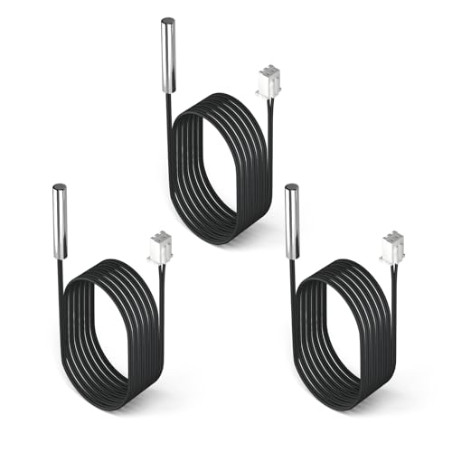
DROK 10K Temperature Sensor Probe 3pcs, 1…
- Advanced Technology: DROK smart sensors cable adopts sensitive and reliable NTC thermistor and connected by PVC wire, 1 meter lead…
- Wide Measuring Range: Our temperature probe is able to tolerate the widest measuring range (-25°c to 125°c (-13℉ to 257℉)).
- Stainless Steel Probe: This temperature sensor for car has 5*25mm stainless steel housing, which is waterproof, moisture-proof and…
If you’re working on a project that needs reliable, repeatable temperature sensing right now, a solid DROK 10K NTC temperature sensor probe is a practical pick. It’s a stainless steel, waterproof thermistor with a 1-meter lead, rated from -25°C to 125°C, and it handles the 3-5V range most microcontrollers use. It won’t win any awards for extreme high-temperature work, but for HVAC, automotive, or hobbyist enclosures, it’s the kind of component that just works.
The Accuracy Bottleneck: Why Traditional Sensors Fail
Platinum RTDs and type-K thermocouples dominate industrial sensing for good reasons. They’re repeatable, they’re cheap, and there’s decades of data on their behavior. But they all hit a wall. The wall is material instability.
Take a standard platinum RTD. At temperatures above 500°C, platinum starts to oxidize and migrate at the grain boundaries. The resistance curve shifts, and your calibration drifts. The drift isn’t catastrophic at first, but over a few hundred thermal cycles, it becomes a real problem. Type-K thermocouples have their own issue: the nickel-chromium alloy oxidizes unevenly, causing a phenomenon called thermoelectric drift that can throw readings off by several degrees.
The core problem is that traditional materials change their physical properties over time under thermal stress. You’re not measuring temperature anymore. You’re measuring the sensor’s history.
This is where new materials change the game. They don’t just improve resolution or response time. They resist the failure modes that make legacy sensors lie to you.
Breakthrough Materials Redefining Thermal Measurement
Three material families are driving the shift in high-accuracy temperature sensing: wide-bandgap semiconductors, carbon nanostructures, and doped ceramic oxides. Each solves a different part of the accuracy problem.
Silicon Carbide and Wide-Bandgap Semiconductors
Silicon carbide (SiC) is the poster child for high-temperature sensing. Traditional silicon electronics die above 150°C. SiC junctions operate reliably at 600°C and above. That’s not an incremental improvement; it’s a completely different operating envelope.
Why does this matter for accuracy? Because you no longer need to place the sensing electronics remotely. You can put the signal conditioning circuitry right at the measurement point. Shorter lead wires mean less noise and less resistance error. A SiC-based sensor can measure temperatures in jet engine exhaust or industrial furnaces with a response time under 100 milliseconds, where a thermocouple with long leads might lag by seconds.
The trade-off? SiC sensors are expensive to manufacture, and they require specialized packaging. You won’t see them in a $20 temperature logger. But for high-value processes where a few degrees of error costs thousands of dollars, the price is justified.
Graphene and Nanostructured Coatings
Graphene has been hyped for everything from batteries to water filters, but temperature sensing is one place where it genuinely delivers. A single layer of graphene has a temperature coefficient of resistance that’s both large and highly linear. More importantly, it doesn’t suffer from the oxidation and interdiffusion that plague metal films.
Graphene sensors excel in two areas: cryogenics and flexible applications. At temperatures below 10K, platinum RTDs become non-linear and hard to calibrate. Graphene maintains a usable response down to millikelvin ranges. That makes it valuable for quantum computing research and space-based instruments.
Nanostructured coatings, like thin films of yttria-stabilized zirconia, are another angle. These coatings protect the underlying sensing element from chemical attack and thermal shock. A coated sensor can survive aggressive environments—sulfuric acid vapors, molten salt, high-vibration settings—that would destroy an uncoated element in weeks.
It’s not perfect. Graphene sensors are notoriously difficult to manufacture consistently at scale. The resistance of a graphene film depends heavily on the number of layers and the substrate, which means batch-to-batch variation is a real headache for calibration.
The Shift from Analog to Smart: IoT and Wireless Integration
New materials don’t just change the physics of sensing; they enable a different architecture for measurement systems. When you use a SiC or graphene element, you can integrate the analog-to-digital converter, the cold-junction compensation, and the wireless transmitter onto the same chip or into the same probe housing.
This matters for accuracy in a way that’s easy to miss. Traditional temperature measurement sends a tiny analog voltage or resistance change down long wires to a central controller. Those wires pick up electromagnetic noise, and the resistance of the wire itself adds error. A smart sensor digitizes the reading at the point of measurement and transmits a digital signal. The noise problem basically disappears.
For industrial manufacturing, this means you can deploy a mesh of wireless temperature sensors across a plant and get consistent accuracy without running miles of shielded cable. For aerospace, it means embedding sensors in composite structures during layup, then monitoring the health of the part throughout its life. The recent advances in flexible temperature sensors show how these materials are being adapted for wearable and structural health monitoring applications.
The catch is power. Wireless sensors need batteries or energy harvesting, and the electronics add cost. You’re trading a long-term accuracy problem for a short-term power management problem. In most cases, that’s a good trade.
Real-World Performance: Drift, Stability, and Calibration
Accuracy isn’t just about the initial reading. It’s about whether the reading stays true after a year of thermal cycling, vibration, and humidity. This is where new materials separate themselves from the legacy options.
Platinum RTDs are the reference standard for stability, with drift rates as low as 0.001°C per year under ideal conditions. But that stability comes with a narrow temperature range and a high price for the best grades. Silicon carbide sensors show drift rates that are competitive with platinum, but they extend the usable range by several hundred degrees.
Doped ceramics, like lanthanum-doped barium titanate, are interesting because they can be engineered for a specific temperature window. You can tailor the dopant concentration to make a sensor that’s incredibly stable between 100°C and 200°C, even if it’s less accurate outside that range. That’s useful for applications like battery thermal management, where you care deeply about a narrow band.
Calibration is another story. The ITS-90 standard defines calibration points based on the behavior of pure substances. Most new materials don’t have the same well-characterized reference data that platinum does. You’ll need to calibrate against a known reference, and you may have to do it more often in the first few months of use until the sensor’s drift stabilizes.
One practical tip: when you get a new sensor made from an exotic material, run it through a burn-in period. Cycle it from room temperature to your maximum operating temperature and back, at least ten times, before you do a final calibration. This stabilizes the microstructure and reduces the initial drift that catches people off guard.
For a deeper look at how to manage these factors, check out this guide on sensor reliability factors.
Cost vs. Value: Calculating the ROI of Next-Gen Sensors
Let’s talk money. A standard type-K thermocouple costs maybe $15. A high-accuracy RTD costs $100. A silicon carbide sensor with integrated electronics? You’re looking at $300 to $500 per sensing point, depending on volume.
That price gap scares people away, but it’s worth doing the math on what a sensor failure actually costs you. If a thermocouple drifts by 5°C in a heat-treating furnace, and that causes a batch of aerospace parts to miss their metallurgical spec, you’re scrapping parts worth thousands of dollars. One rejected batch pays for dozens of premium sensors.
Here’s a simple framework for the calculation:
- Estimate your current sensor drift rate in degrees per year.
- Estimate the cost of a process deviation of that magnitude (scrap, rework, downtime).
- Multiply that cost by the number of sensors you run.
- Compare that total to the premium you’d pay for lower-drift sensors.
In high-mix, low-volume manufacturing, the calculation often favors staying with cheap sensors and just recalibrating more often. In continuous processes with high throughput, the premium sensors pay for themselves in months.
One thing to watch: the calibration cost for exotic sensors can be higher. You might need a specialized lab or a higher-grade reference standard. Factor that into the total cost of ownership, not just the sticker price.
If you’re retrofitting an existing system, also consider the installation cost. Smart sensors need different wiring or no wiring at all, which can save thousands on cable and labor. That’s often the hidden win.
Future Trends: Miniaturization and Predictive Maintenance
The next five years will bring two big shifts. First, miniaturization. We’re already seeing temperature sensors that fit on the tip of a needle, using thin-film technology on a ceramic substrate. These tiny sensors have fast response times—milliseconds, not seconds—because they have very little thermal mass. They’re ideal for biomedical applications and for measuring temperature gradients in microelectronics.
Second, predictive maintenance. When a sensor has on-board processing, it can track its own drift. A smart sensor that recognizes its resistance baseline shifting over time can flag itself for recalibration before it produces an out-of-spec reading. That’s a huge advance over the current practice of scheduled recalibration, which either wastes time or misses failures depending on how conservative your schedule is.
The future of temperature sensors in manufacturing is heading toward self-diagnosing networks. The materials are the enabling factor because they provide the stability needed for the electronics to track drift meaningfully. A sensor that drifts randomly can’t be self-diagnosed; one that drifts predictably can.
For more on how material choices affect your measurement strategy, this piece on temperature sensor accuracy considerations is a good companion read.
Making the Right Material Choice for Your Application
So what should you actually do? Here’s the practical breakdown.
- Stick with thermocouples if your process tolerates ±5°C and you can recalibrate monthly. They’re still the cheapest option per point.
- Upgrade to RTDs if you need ±0.5°C and you’re below 500°C. The cost is moderate and the reference data is solid.
- Consider SiC or wide-bandgap sensors if you’re above 500°C or you need fast response in a noisy environment. The cost is high, but the reliability payoff is real.
- Look at graphene or thin-film sensors for cryogenic work, flexible applications, or anywhere you need to measure a tiny thermal mass.
- Always run a burn-in cycle before final calibration, regardless of material.
- Track drift over time with a simple log. Two data points a year will tell you more than any spec sheet.
- Budget for calibration as a recurring cost, not a one-time setup. The material determines how often you need it.
The accuracy revolution in temperature sensing isn’t coming from better algorithms. It’s coming from materials that hold their physical properties steady under extreme conditions. That’s a change you can measure.
Frequently Asked Questions
How much more accurate are new materials compared to a standard thermocouple?
A standard type-K thermocouple is rated at ±2.2°C accuracy in the mid-range. A high-grade RTD gets you to ±0.1°C. A silicon carbide sensor with integrated electronics can hit ±0.2°C at temperatures where a thermocouple would be off by 5°C or more. The real advantage is stability over time, not just the initial accuracy spec.
Do I need to change my calibration equipment for these new sensors?
Probably not. Most calibration baths and dry-block calibrators work fine for any sensor that fits in the well. The bigger issue is the calibration interval. New materials may need a shorter initial interval until you establish their drift rate. After that, you can often extend the interval beyond what you used for thermocouples.
Can I use a graphene sensor in a high-vibration environment?
Yes, and it’s actually one of their strengths. Graphene films are mechanically robust and don’t crack under vibration the way brittle ceramic elements might. The challenge is the packaging. Make sure the sensor is hermetically sealed and the electrical contacts are strain-relieved. Vibration can cause intermittent contact failures that look like temperature spikes.
What’s the best material for measuring temperatures below -40°C?
For cryogenic work, platinum RTDs are still the standard down to about 20K, but they become non-linear below that. Graphene-based sensors maintain better linearity at millikelvin temperatures. For the range from -40°C to -100°C, a standard NTC thermistor like the DROK probe works fine and costs a fraction of the exotic options. The key is to check the sensor’s resistance-temperature curve in that region; some NTCs get very non-linear near their lower limit.
How do I know if my sensor drift is due to the material or the installation?
Run a controlled test. Take a known-good reference sensor and mount it next to the suspect sensor in the same thermal environment. Log both readings over a week. If the difference grows over time, it’s the sensor material. If the difference is constant but offset, it’s likely a mounting or thermal-contact issue. If the difference is random, suspect electrical noise or a wiring problem.

I am a mechanical engineer and love doing research on different home and outdoor heating options. When I am not working, I love spending time with my family and friends. I also enjoy blogging about my findings and helping others to find the best heating options for their needs.
Related guides

Essential Automotive Temperature Sensors for Peak Performance
You're chasing a misfire that only shows up after 20 minutes of highway driving. The factory gauge reads…
How Temperature Sensors Boost HVAC Efficiency and Comfort
Temperature sensors in HVAC systems monitor and regulate indoor climate, ensuring efficient heating and cooling for optimal comfort…

How to Test Temperature Sensor Performance Accurately
To test temperature sensor performance, use a calibrated reference thermometer, compare readings, and assess accuracy, response time, and…