To make a temperature-controlled fan using Arduino, connect a temperature sensor and a relay module to control the fan based on the sensor’s readings.
Create an automated cooling system that adjusts fan speed based on real-time temperature readings. This Arduino project combines simple electronics with practical programming for efficient thermal management.
Essential Components for Your Arduino Fan Controller
You’ll need these core components to build your temperature-controlled fan:
- Arduino Uno or Nano board
- LM35 temperature sensor (or DHT22 for higher accuracy)
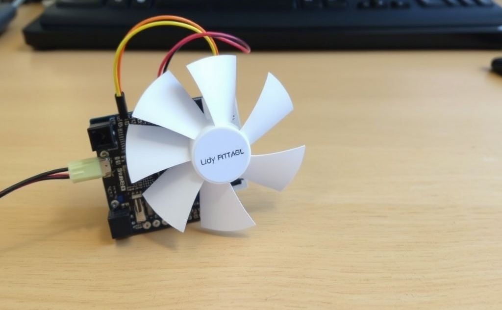
- 12V DC fan with PWM capability
- 2N2222 transistor or MOSFET (IRF520 works well)
- 16×2 LCD display (optional for visual feedback)
- 1kΩ resistor and 10kΩ potentiometer
- Breadboard and jumper wires
For more advanced thermal projects, consider exploring water heater thermostat control systems which use similar principles.

Circuit Design and Connections
Temperature Sensor Setup
The LM35 provides 10mV per °C, making it ideal for Arduino projects:
- Connect LM35 VCC to Arduino 5V
- Attach GND to Arduino ground
- Link output to analog pin A0
Fan Control Circuit
Use this configuration for safe fan operation:
| Component | Connection |
|---|---|
| Transistor Base | Arduino PWM pin (D9) via 1kΩ resistor |
| Transistor Collector | Fan negative wire |
| Transistor Emitter | Ground |
| Fan positive | 12V power supply |
Programming Your Arduino
This code provides smooth fan speed adjustment:
const int tempPin = A0;
const int fanPin = 9;
int minTemp = 25; // Fan starts at 25°C
int maxTemp = 50; // Full speed at 50°C
void setup() {
 pinMode(fanPin, OUTPUT);
 Serial.begin(9600);
}
void loop() {
 int reading = analogRead(tempPin);
 float voltage = reading * (5.0 / 1024.0);
 float tempC = voltage * 100; // LM35 conversion
 int fanSpeed = map(tempC, minTemp, maxTemp, 0, 255);
 fanSpeed = constrain(fanSpeed, 0, 255);
 analogWrite(fanPin, fanSpeed);
 Serial.print("Temperature: ");
 Serial.print(tempC);
 Serial.print("°C | Fan Speed: ");
 Serial.println(fanSpeed);
 delay(1000);
}
Advanced Features to Implement
Hysteresis Control
Prevent rapid fan cycling by adding 2-3°C buffer between on/off thresholds.
LCD Display
Add real-time feedback with a 16×2 LCD showing both temperature and fan speed percentage.
Multiple Fan Control
Expand the system to manage several fans in larger cooling applications, similar to industrial heater blower systems.
Troubleshooting Common Issues
If your fan isn’t responding correctly:
- Verify all electrical connections match your schematic
- Check transistor orientation (flat side facing correct direction)
- Ensure power supply can handle fan current draw
- Test temperature sensor with serial monitor output
- Confirm PWM signal with multimeter or oscilloscope
For more complex thermal regulation projects, study LM35 datasheet from Texas Instruments to understand sensor characteristics.
Practical Applications
This temperature-controlled fan has multiple uses:
- Computer case cooling system
- Greenhouse temperature regulation
- Electronics workshop ventilation
- 3D printer enclosure cooling
- Food storage area climate control
The same principles can be adapted for various thermal management needs, from small electronics to larger environmental controls.
