

To integrate sensors with PLC systems, connect the sensor outputs to the PLC input terminals, configure the PLC to read the signals, and program the logic accordingly.
Connecting sensors to Programmable Logic Controllers (PLCs) is a fundamental skill for automation engineers. This guide covers everything from wiring basics to advanced integration techniques for industrial applications.

CG CHIPS GATE
NEW WL250-2P2431 PHOTOELECTRIC Retro-Reflective Sensor PLC Module
- Founded in 2010, Chips Gate is a trusted supplier of industrial automation equipment, including PLC modules,motor drives, and cont…
- Wide selection of automation equipment suitable for various industrial and commercial applications.
- Durable packaging keeps your order fully protected in transit.
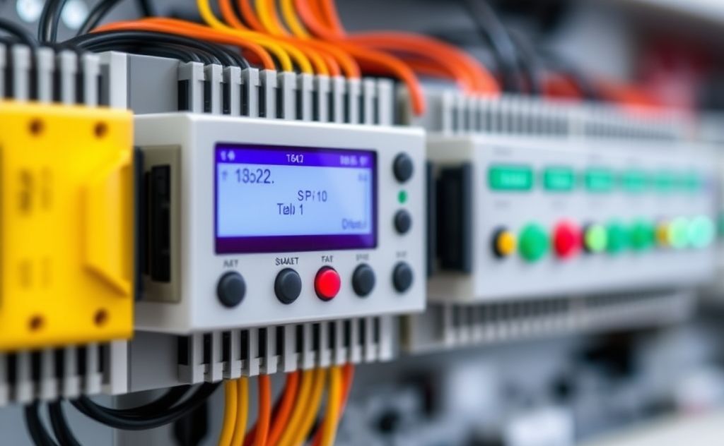
Understanding Sensor-to-PLC Connections
PLC systems rely on sensor inputs to monitor and control industrial processes. Proper integration ensures accurate data collection and system reliability.
Types of Sensors for PLC Integration
- Discrete sensors: Simple on/off devices like pushbuttons and limit switches
- Analog sensors: Provide variable signals like 4-20mA or 0-10V outputs
- Smart sensors: Digital devices with communication protocols like IO-Link
Power Requirements
Most industrial PLC systems use 24VDC power supplies. The water heater thermostat control demonstrates similar voltage requirements for industrial components.
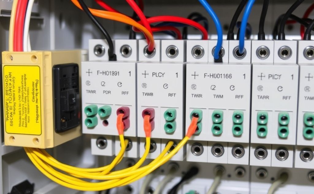
Wiring Sensors to PLC Input Cards
Proper wiring is critical for reliable operation. Follow these steps for successful integration.
2-Wire DC Sensor Connection
- Identify sensor polarity (if polarized)
- Connect positive wire to PLC input terminal
- Connect negative wire to common terminal
- Verify wiring with multimeter
3-Wire Sensor Connection
| Wire Color | Connection |
|---|---|
| Brown | 24V+ |
| Blue | 0V |
| Black | Signal to PLC |
PLC Input Card Configuration
Different sensor types require specific PLC input card configurations.
Digital Input Cards
Used for discrete sensors. The pool heater control panel uses similar digital inputs for status monitoring.
Analog Input Cards
Process variable signals from sensors like:
- Pressure transmitters
- Temperature sensors
- Flow meters
Advanced Integration Techniques
Modern systems offer more sophisticated connection methods.
IO-Link Communication
IO-Link provides digital communication with smart sensors while using standard 3-wire cabling. According to Control Engineering, this technology simplifies sensor integration.
Wireless Sensor Networks
For hard-to-reach locations, wireless solutions like ISA Wireless can connect sensors to PLCs without cabling.
Troubleshooting Sensor Connections
Common issues and solutions when integrating sensors with PLCs.
No Signal Detection
- Check power supply voltage
- Verify wiring connections
- Inspect sensor status LEDs
- Test with known good sensor
Signal Fluctuations
- Check for loose connections
- Verify proper grounding
- Inspect for electromagnetic interference
- Consider shielded cables
Best Practices for Reliable Operation
Follow these guidelines for robust sensor-PLC integration.
Cable Management
- Use proper cable glands and strain relief
- Separate power and signal cables
- Label all connections clearly
Documentation
Maintain accurate records of:
- Sensor specifications
- Wiring diagrams
- PLC addressing
- Calibration data
Related pick: Check today's price on Amazon

I am a mechanical engineer and love doing research on different home and outdoor heating options. When I am not working, I love spending time with my family and friends. I also enjoy blogging about my findings and helping others to find the best heating options for their needs.
Related guides

Industrial Temperature Sensors: The Key to Process Control
Walk into any plant floor and you'll see them: thermowells sticking into pipes, probe heads bolted to reactor…

Top Temperature Sensors for Accurate Environmental Monitoring
Temperature sensors for environmental monitoring accurately measure air, soil, and water temperatures, ensuring effective climate data collection and…

How to Choose the Right Temperature Sensor for Any Application
You need to measure temperature in a process, a room, or a piece of equipment. Walk into any…
