
You walk up to a panel that reads 250 F when the oven door is open and the room feels like 70. Your first instinct is to swap the sensor. I have been there myself – and most of the time the sensor was fine. The problem turned out to be a loose terminal, a corroded connector, or a ground loop I had ignored. Replacing a good sensor wastes money and downtime, and it teaches you nothing.
This article covers how to troubleshoot temperature sensors like a pro. You ll learn which signals to trust, which measurements to take, and two common myths that send technicians down the wrong path. By the end you ll have a repeatable process that works for thermocouples, RTDs, and 4-20 mA transmitters.
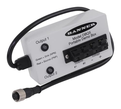
A portable test tool can save hours in the field. The Banner Engineering DBQ5 Portable Demo Box powers DC self-contained sensors and shows output with bi-color LEDs. It tells you instantly whether the sensor is alive and responding to temperature changes, without tying into your control system. It is not a full calibrator, but it cuts the guesswork in half when you want a quick go / no-go check.
Myth #1: A Bad Reading Means a Bad Sensor
This is the single most expensive mistake in industrial maintenance. A thermocouple produces only microvolts per degree. A PT100 RTD changes resistance by about 0.38 ohms per degree. Tiny signals are vulnerable. A 60 Hz hum from a nearby motor drive can swamp a 0.2 mV thermocouple signal completely. The display will show wild numbers or a stuck value, but the sensor is fine.
Before blaming the element, check the wiring path. Look for broken strands inside insulation, loose screw terminals, and corrosion on connectors. Use a multimeter to measure the sensor resistance at the instrument end. For a PT100 at room temperature (25 C) you should see roughly 109.7 ohms. If you see infinite resistance, the wire is open. If you see a few ohms, a short. If you see the right resistance but the display is wrong, the problem is elsewhere – likely the input card, the cable shield, or a ground loop. A quick loop test with a milliamp source can confirm the transmitter side.
Myth #2: You Can Skip Cold-Junction Compensation for Thermocouples
A thermocouple does not measure absolute temperature. It measures the voltage difference between the measuring junction and the reference junction (where the thermocouple wire connects to the instrument). If the instrument assumes the reference junction is at 0 C but it is actually at 25 C, your reading will be off by 25 C – often more because the voltage curve is not perfectly linear.
I once watched a technician spend two hours replacing a Type K thermocouple because the room temperature had risen from 20 to 30 C and the reading drifted. The sensor was fine. The instrument s cold-junction compensation (CJC) was working, but the ambient shift caused a 10 C error that looked like a sensor drift. A quick test: short the thermocouple input with a copper wire. The instrument should read its own internal temperature (minus some small offset). If it does, the CJC circuit is alive. If not, the problem is in the instrument, not the sensor. Every serious thermocouple trouble-shooter should verify CJC before pulling the probe.
The Systematic Troubleshooting Sequence
Here is a process I use that catches 90 percent of temperature signal problems in under ten minutes. It works for most common sensor types.
- Visual inspection. Examine the probe tip for damage, the connection head for moisture, and the terminal block for loose screws or corrosion. This alone finds about one-third of failures.
- Resistance measurement. For RTDs, measure resistance across the element at ambient temperature. Compare to the standard tables. For a PT100: 100 ohms at 0 C, 138.5 ohms at 100 C, 175.8 ohms at 200 C. Allow for the tolerance (±0.12 ohms for Class A). For thermocouples, measure resistance across the wires – it should be a few ohms. High resistance indicates damaged wire or a poor connection.
- mV source simulation. Disconnect the sensor and connect a precision mV source (or a calibrator) to the instrument input. Set the source to a known mV value from a temperature table. If the instrument reads the correct temperature, the sensor cable and input card are good. If it reads wrong, the instrument or its settings need attention.
- Loop current test. For 4-20 mA transmitters, measure the loop current with a meter in series. At room temperature, expect about 12 mA for a 0-100 C range with 50 C ambient. If the current is wrong but the sensor resistance is correct, the transmitter is faulty or misconfigured.
For quick field checks, the field calibration steps detailed in another guide cover the calibrator method in more depth. If you want to understand the physics behind each signal type, the temperature sensor basics article is a good background read.
Comparison of Troubleshooting Methods
| Method | What It Checks | Tools Needed | Typical Time |
|---|---|---|---|
| Visual inspection | Physical damage, loose wires, corrosion | Eyes, flashlight | 2 minutes |
| Resistance measurement | Continuity, element integrity | Multimeter | 3 minutes |
| mV source simulation | Instrument input side, wiring | Precision mV source or calibrator | 5 minutes |
| Loop current test | Transmitter output, loop power | mA meter, power supply | 4 minutes |
| Demo box substitution | Sensor output, response to temp | Banner DBQ5 or similar | 2 minutes |
The table shows that most checks take under five minutes. The demo box is the fastest because it does not require disconnection from the system – you just place it near the sensor face and watch the LEDs. But it only works with DC self-contained sensors that match the box s power spec.
Five Questions People Really Ask
Why does my temperature sensor read negative when it is hot?
Most likely the wires are reversed at the input. A thermocouple is polarity-sensitive. Reverse the two wires at the instrument terminal and the reading will swing negative. For RTDs, a reversed connection gives a low or negative reading because the lead resistance cancels incorrectly. Check the wiring diagram. Also look for a broken shield that puts a positive voltage onto the signal wire – that can offset the reading below zero.
Can I use a multimeter to test a thermocouple?
You can measure resistance but not voltage accurately. A standard multimeter draws enough current during voltage measurement to load a thermocouple s microvolt signal, giving a false reading. Use a meter with a microvolt range or a dedicated thermocouple calibrator. For a quick check, measure DC millivolts with the meter set to the lowest range – if you see a few millivolts when the sensor is hot, the element is likely good. But do not trust the number. For a proper test, use a simulator.
What is the difference between a 2-wire, 3-wire, and 4-wire RTD and does it matter for troubleshooting?
It matters a lot. A 2-wire RTD measures the element resistance plus the lead resistance. In a long cable run the lead resistance can add several ohms, causing a several-degree error. A 3-wire RTD cancels lead resistance using a third wire and a bridge circuit. A 4-wire RTD uses separate current and sense wires for the most accurate measurement. When troubleshooting, if you see a steady offset, check whether the instrument is set for the correct wiring configuration. Swapping a 2-wire sensor into a 3-wire input will produce a wrong reading even if both parts are fine.
My temperature reading jumps around randomly. What should I check first?
Random jumps usually indicate electrical noise. Shield the sensor cable and ground the shield at one end only (the instrument end). Avoid running signal cables parallel to power cables. If the noise persists, add a capacitor across the instrument input – a 0.1 µF film capacitor often cleans up high-frequency noise. Also check for a failing power supply that is putting ripple onto the loop. A steady supply should show less than 50 mV AC ripple.
How do I know if my RTD has drifted out of tolerance?
Measure its resistance in ice water (0 C) and compare to the nominal value of 100 ohms. For a PT100, a drift of more than 0.3 ohms (about 0.8 C) indicates the element has aged or been mechanically shocked. For a higher accuracy check, use a calibrated dry block at two or three points. A drift of 0.5 C or more at 100 C usually warrants replacement, but check your application tolerance first – many processes can handle a degree of drift.
Things to Remember Next Time You Suspect a Bad Sensor
- Never replace a sensor without measuring its resistance or signal first. The problem is often the wiring or the input card.
- Always verify cold-junction compensation for thermocouples by shorting the input with copper wire – the reading should equal the instrument s internal temperature.
- Use a portable demo box like the Banner DBQ5 for a fast go / no-go check on DC self-contained sensors. It only takes two minutes.
- Keep a set of sensor tables for PT100, Type K, and Type J handy. Print them out. You ll use them more than any app.
- When you see a random jumping reading, suspect noise before hardware failure. Check shield grounding and cable routing.
- For 4-20 mA loops, measure the current with the sensor at room temperature. A wrong current combined with correct sensor resistance points to a faulty transmitter.
- Document every test you run. When the same sensor acts up again, you ll have a history that shows what was already ruled out. That is how pros troubleshoot temperature sensors efficiently.